
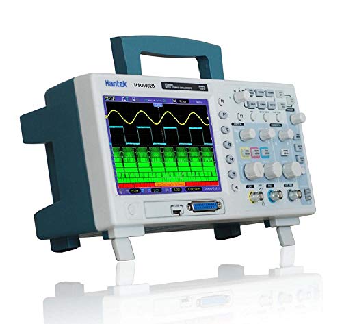
HANTEK MSO5102D Digital Oscilloscope 100 Mhz
| รหัสสินค้า | 00545 |
| หมวดหมู่ | Digital Ossilloscope |
| ราคา | 15,390.00 บาท |
| น้ำหนัก | 2,080 กรัม |
| ยี่ห้อ | Hantek |
| รุ่น | MSO5102D |
| ขนาด | 385 x 200 x 245 mm. |
| สถานะสินค้า | Pre-Order |
| สภาพ | สินค้าใหม่ |
| ลงสินค้า | 21 พ.ย. 2562 |
| อัพเดทล่าสุด | 4 มิ.ย. 2568 |
| คงเหลือ | ไม่จำกัด |
| จำนวน | EA |
หยิบลงตะกร้า

รายละเอียดสินค้า
| model | MSO5202D | MSO5102D | MSO5062D |
| collection | |||
| Sampling type | Real-time sampling: 1GSa/s | ||
| Collection method | |||
| sampling | Sampled data | ||
| Peak to peak | Display high frequency and random glitch | ||
| average value | Average waveform, number of times: 4, 8, 16, 32, 64, 128 | ||
| Input | |||
| Input coupling | DC, AC or ground (DC, AC, GND) | ||
| input resistance | 1MΩ±2% ‖20pF±3pF | ||
| Probe attenuation | 1X, 10X | ||
| Probe attenuation coefficient setting | 1X, 10X, 100X, 1000X | ||
| Maximum input voltage | Type I and Type II: 300VRMS (10×); Mounting Type III: 150VRMS (1×); Mounting Type II; AC peak with a slope of 20 dB/decade from 100 kHz to 3 MHz* 13 V. For non-sinusoidal waveforms, the peak value must be less than 450 V. The offset duration above 300 V should be less than 100 ms. The RMS signal level (including all DC components removed by AC coupling) must be limited to 300 V. If these values are exceeded, the instrument may be damaged. |
||
| Horizontal system | |||
| Sample rate range | 500MS/s--1GS/s | ||
| Waveform interpolation | (sin x)/x | ||
| Storage depth | Single channel up to 1M, dual channel 512K (4K, 40K optional) | ||
| Scanning range | 2ns/div~40s/div | 8ns/div~40s/div | |
| Sampling rate and delay time accuracy | ±50ppm (at any time interval greater than 1ms) | ||
| Location range | 2ns/div to 8ns/div; (-4div xs/div) to 20ms; | 20ns/div to 80us/div; (-8div xs/div) to 40ms; 200us/div to 40s/div; (-8div xs/div) to 400s; |
|
| Time interval measurement accuracy (full bandwidth) | Single: ± (1 sample interval + 500ppm x reading + 0.6ns); > 16 average values: ± (1 sample interval + 500ppm x reading + 0.4ns); sampling interval = seconds / grid ÷ 200 |
||
| Vertical system | |||
| Vertical resolution | 8-bit resolution, simultaneous sampling for each channel | ||
| Vertical sensitivity | 2mV/div to 10V/div | ||
| bandwidth | 200MHz | 100MHz | 60MHz |
| Rise time at the BNC | 1.8ns | 3.5ns | 5.8ns |
| Offset range |
2mV/div to 20mV/div, ±400mV 50mV/div to 200mV/div, ±2V 500mV/div to 2V/div, ±40V 5V/div to 10V/div, ±50V |
||
| computation | Add, subtract, multiply, divide, FFT | ||
| FFT | Windows: Hanning, Flatop, Rectamgular, Bartlett, Blackman; 1024 sample points | ||
| Bandwidth limit | 20MHz | ||
| Low frequency response (-3db) | ≤10Hz at the BNC | ||
| Vertical gain accuracy | In the "sampling" or "average" acquisition mode, the accuracy of 10V / grid to 10mV / grid is ± 3%; in the "sampling" or "average" acquisition mode, the accuracy of 5mV / grid to 2mV / grid is ± 4 % |
||
| DC measurement accuracy, average acquisition mode | The vertical displacement is zero, and when N≥16: ±(3%×reading+0.1 +1+1V), suitable for selecting units of 10 mV/div or larger. When the vertical displacement is not zero, and N≥16: ±[3%×(reading + vertical position) + 1%+0.2 grid of vertical position). Set 2mV from 2mV/div to 200mV/div; increase 50mV from 200mV/div to 10V/div |
||
| Voltage measurement repeatability, average acquisition mode | Accumulate voltage increments between any two groups of ≥16 or more waveforms under the same settings and environmental conditions: ± (3% × reading + 0.05 cells) | ||
| Trigger system | |||
| Trigger type | Edge, video, pulse, slope, timeout, alternation, pattern, persistence, queue, repeat | ||
| Trigger source | CH1, CH2, EXT, EXT/5, AC Line, D0-D15 | ||
| Trigger mode | Automatic, normal, single | ||
| Coupling method | DC, AC, noise suppression, high frequency rejection, low frequency rejection | ||
| Trigger sensitivity (edge trigger type) | DC (CH1, CH2): 1 grid from DC to 10MHz; 1.5 grids from 10MHz to 100MHz; 2 grids from 100MHz to maximum range; DC (EXT): 200mV from DC to 100MHz; from 100MHz to 350mV maximum range ; DC (EXT / 5): from DC to 100MHz is 1V; maximum range is from 1.75V to 100MHz; AC: signal attenuation below 10Hz; HF rejection: greater than 80kHz when the attenuated signal; low inhibition: 150kHZ frequency is greater than, Same as DC coupling limit, less than 150kHZ; |
||
| Trigger level range | CH1, CH2: ±8 divisions from the center of the display; EXT: ±1.2V; EXT/5: ±6V |
||
| Trigger level accuracy (typical) relative to signals with rise and fall times greater than or equal to 20ns | CH1, CH2: 0.2 cells × volts/division within ±4 divisions from the center display; EXT: ± (6% set value + 40mV); EXT/5: ± (6% set value + 200mV ); |
||
| Set the level to 50% (typical) | Operate with an input signal greater than or equal to 50 Hz | ||
| Video trigger | |||
| Video trigger type | CH1, CH2: peak-peak amplitude of 2 divisions; EXT: 400mV; EXT/5: 2V |
||
| Signal format and field rate, video trigger type | Support NTSC, PAL and SECAM for any field or any line | ||
| Release range | 100ns ~ 10s | ||
| Pulse width trigger | |||
| Pulse width trigger mode | Trigger when (< , >, =, or ≠); "positive" pulse or "negative" pulse | ||
| Pulse width trigger point | Equal to: The oscilloscope triggers when the falling edge of the pulse crosses the trigger level. Not equal: If the pulse is narrower than the specified width, the trigger point is the falling edge. Otherwise, when the pulse duration is longer than the "pulse width" when the specified time, the oscilloscope is triggered. Less than: trigger point is the trailing edge is greater than (also called time-out trigger): When a pulse duration between longer than the "pulse width" specified When the time is up, the oscilloscope triggers. |
||
| Pulse width range | 20ns ~ 10s | ||
| Slope trigger | |||
| Slope trigger mode | Trigger when (<, >, =, or ≠); "positive" slope or "negative" slope | ||
| Slope trigger point | Equal to: The oscilloscope triggers when the slope of the waveform is equal to the set slope. Not equal to: The oscilloscope triggers when the slope of the waveform is not equal to the setting. Less than: The oscilloscope triggers when the slope of the waveform is less than the set slope. Greater than: The oscilloscope triggers when the waveform slope is greater than the set slope. |
||
| Time setting range | 20ns ~ 10s | ||
| Timeout trigger | |||
| Timeout trigger mode | Rising edge | ||
| Time setting range | 20ns ~ 10s | ||
| Alternate trigger | |||
| CH1 | Internal trigger: edge, pulse width, video, slope | ||
| CH2 | Internal trigger: edge, pulse width, video, slope | ||
| Trigger frequency counter | |||
| Reading resolution | 6 digits | ||
| Accuracy (typical) | ±30ppm (including all frequency reference errors and ±1 calculation error) | ||
| Frequency Range | AC coupling, from a minimum of 4 Hz to a nominal bandwidth | ||
| signal source | “Pulse Width” or “Edge Trigger” mode: All available trigger sources “Frequency Counter” are always measuring the trigger source, including when the oscilloscope acquisition is paused due to a change in the operating state, or when a single event acquisition has ended Time. “Pulse Width” trigger mode, the oscilloscope calculates the measurement at 1 s, the window has a valid amplitude, and matches the pulse that can trigger the event condition, for example, if the PWM pulse train is set to <mode, and the width is set accordingly When there is a small time, there is a narrow pulse. Edge Trigger mode: The oscilloscope calculates all edges with sufficient amplitude and correct polarity. "Video Trigger" mode: "Frequency Calculator" does not work. |
||
| measuring | |||
| Cursor measurement | The voltage difference between the cursors ΔV The time difference between the cursors ΔT ΔT, in Hertz (1/△T) |
||
| Automatic measurement | Frequency, period, average, peak-to-peak, rms, maximum, minimum, rise time, fall time, positive bandwidth, negative bandwidth, rising edge phase difference, falling edge phase difference, positive duty cycle, negative Duty cycle, bottom value, top value, intermediate value, amplitude, overshoot, preshoot, cycle average, period mean square, falling edge overshoot, rising edge preshoot, BWIDTH, FRF, FFR, LRR, LRF, LFR, LFF | ||
| display | |||
| Display type | 7'' TFT true color LCD screen | ||
| Resolution | 800*480 dots | ||
| Display contrast | 16-speed adjustable and on-screen display adjustment progress bar | ||
| Logic Analyzer Specifications | |||
| Number of sampling channels | 16 channels | ||
| Input maximum impedance | 200K (C=10p) | ||
| Input voltage range | -60V~60V | ||
| Logic gate range | -8V~8V | ||
| Maximum sampling rate | 500MHz | ||
| Compatible input | TTL, CMOS, ECL | ||
| Sampling depth | 512K | ||
| trigger | |||
| Edge trigger | D0-D15 selects the slope (rising edge or falling edge) | ||
| Slope trigger | D0-D15 select pulse polarity (positive pulse or negative pulse), pulse trigger timing (=, ≠, <, >), trigger pulse width | ||
| Pattern trigger | D0-D15 selects the pattern (H, L, X) | ||
| Continuous trigger | D0-D15 select duration and trigger timing (data end, data start and data delay) | ||
| Queue trigger | D0-D15 select specific data index (0-3) and pattern (H, L, X) | ||
| repeat times | D0-D15 selects the pattern (H, L, X) and the number of repetitions | ||
| Probe compensator output | |||
| Output voltage (typical) | A load of about 5Vpp input ≥1MΩ | ||
| Frequency (typical) | 1kHz | ||
| power supply | |||
| voltage | 100-120VACRMS (±10%), 45Hz to 440Hz, CATII 120-240VACRMS (±10%), 45Hz to 66Hz, CATII |
||
| power | <30W | ||
| fuse | 2A, T rating, 250V | ||
| surroundings | |||
| temperature range | Operation: 32°F to 122°F (0°C to 50°C); non-operational: -40°F to 159.8°F (-40°C to +71°C) |
||
| cooling method | fan | ||
| Humidity range | +104°F or less (+40°C or less): ≤90% relative humidity; 106°F ~122°F (+41°C ~ 50°C): ≤60% relative humidity |
||
| Altitude | Operation time: 3000 meters (10000 feet) or less; non-operation time: 15000 meters (50,000 feet) or less |
||
| Mechanical specifications | |||
| size | 385mm x 200mm x 245mm | ||
| weight | 3.5KG (including packaging); 2.08KG (without packaging) |
||
วิธีการชำระเงิน
ชำระเงินผ่านธนาคาร
ชำระเงินออนไลน์
- ค่าธรรมเนียม 3.9% + 11 THB
- การชำระผ่าน PayPal คุณไม่จำเป็นต้องแจ้งชำระเงิน เนื่องจากระบบจะจัดการให้คุณทันที ที่คุณชำระเงินเสร็จสมบูรณ์
Join เป็นสมาชิกร้านค้า
ร้านหจก.เอส.ซี.ไอซี ซัพพลาย
/www.it-elec.com/
สมัครสมาชิกร้านนี้ เพื่อรับสิทธิพิเศษ


- พิมพ์ “หจก.เอส.ซี.ไอซี ซัพพลาย” ในช่อง Search
- หรือเข้าจากรายการร้านค้าโปรดของฉัน
สินค้าในตะกร้า ({{total_num}} รายการ)

ขออภัย ขณะนี้ยังไม่มีสินค้าในตะกร้า
ราคาสินค้าทั้งหมด
฿ {{price_format(total_price)}}
- ฿ {{price_format(discount.price)}}
ราคาสินค้าทั้งหมด
{{total_quantity}} ชิ้น
฿ {{price_format(after_product_price)}}
ราคาไม่รวมค่าจัดส่ง
➜ เลือกซื้อสินค้าเพิ่ม